
Pneumatic Timers: What Should You Confirm Before Replacing a Timing Unit?

A failed timing unit can seem like an easy part swap until the replacement arrives and the machine still does not cycle correctly. The body may fit, but the delay range, porting, mounting, or timing logic may not match the original application. A replacement pneumatic timer must match the timing range, pneumatic interface, mounting style, and on-delay or off-delay sequencing before purchase to restore the intended machine cycle without unnecessary troubleshooting.
Confirm the Timing Range and Adjustment Style
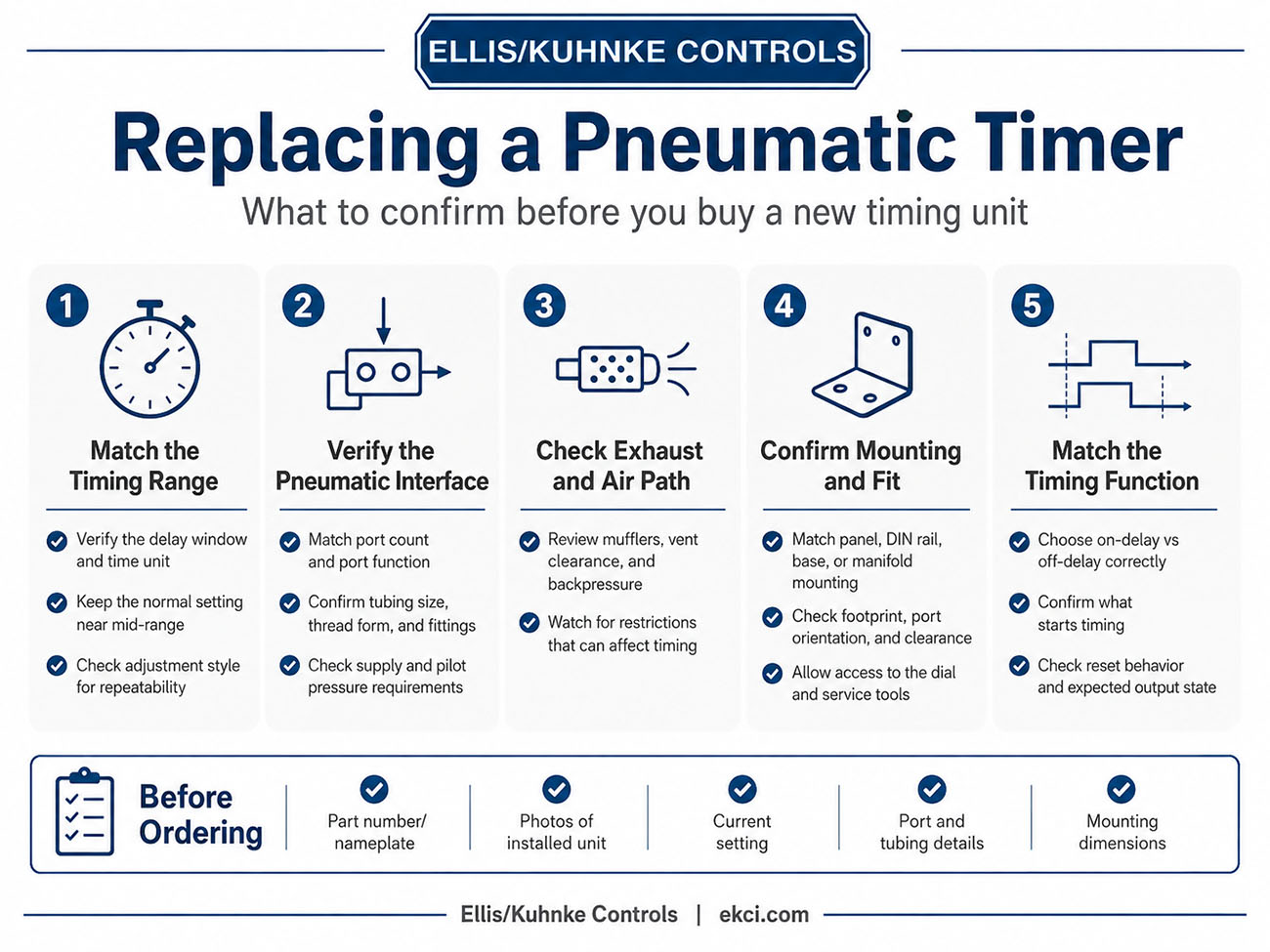
The first compatibility check is whether the replacement can reproduce the same usable delay, not simply whether it has a similar dial. A timer with the wrong span may be impossible to set accurately, especially if the normal operating point falls near the bottom or top of the range. Replacement selection also has to account for how the scale is marked and how finely the setting can be repeated. EKCI/Kuhnke notes that technicians should verify whether the timer is marked in seconds, minutes, or hours by checking labeling or model specifications. They also stress confirming the operating range so numerical settings correspond to actual delays. That matters when old maintenance notes say “set to 5,” but the replacement scale changes from seconds to minutes or from a fine micrometer adjustment to a coarse single-turn knob. The practical takeaway is to match the delay window, time unit, and adjustment style before treating any pneumatic timers as interchangeable.
|
Existing detail to verify |
Replacement requirement |
Compatibility risk if missed |
|
Printed timing range |
Same or appropriately overlapping span |
Timer cannot reach the required delay |
|
Unit of measure |
Seconds, minutes, or hours must align |
Familiar settings produce the wrong time |
|
Adjustment format |
Comparable knob, micrometer, multi-turn, or dual-scale style |
Setpoint becomes harder to repeat |
|
Normal operating setpoint |
Should fall comfortably within the range |
Fine-tuning room is lost |
A good replacement usually places the normal delay near the middle of the adjustment range. That gives maintenance personnel room to account for process changes without having to replace the timer again. The adjustment style should be treated as part of the specification because repeatable setup is often just as important as the catalog timing range.
Verify the Pneumatic Interface
The pneumatic interface determines whether the timer can be installed into the existing air circuit without changing the machine. Port count, port function, tubing size, thread form, and fitting style should be checked against the removed timer and any available machine drawing. A unit with the correct delay can still be wrong if the inlet, outlet, pilot, reset, or exhaust connection requires rerouting tubing or the addition of adapters.
Pressure requirements also need to be confirmed before ordering. The replacement should match the normal supply pressure, minimum pilot signal, allowable maximum pressure, and the original unit's response to reduced or full-pressure signals. Long tubing runs, small fittings, restrictive flow paths, or marginal pilot pressure can cause a replacement timer to behave inconsistently, even when the part appears comparable. Exhaust handling should also be reviewed for any issues with mufflers, vent clearance, contamination control, or backpressure that could affect timing performance.
Check Mounting and Physical Fit
Mounting style is another common source of failed substitutions. Panel-mounted, DIN rail, base-mounted, and manifold-mounted timers may look similar in a catalog but require different installation clearances and hardware. A buyer should compare the footprint, hole pattern, rail clip orientation, port direction, body depth, knob projection, and access for adjustment before assuming a substitute will fit.
- Match panel, DIN rail, base, or manifold mounting style.
- Confirm center-to-center mounting dimensions and fastener size.
- Check port orientation against the existing tubing path.
- Leave clearance for the dial, labels, fittings, and service tools.
- Verify any requirements for adapter plates, gaskets, clips, or subplates.
- Review door clearance and nearby components before ordering.
Physical fit should be evaluated in the installed orientation, not only by catalog dimensions. A timer that technically fits the mounting holes may still block a cabinet door, hide the scale, interfere with a gauge, or force tight tubing bends. These practical details are especially important when replacing obsolete units, as small envelope changes can cause more downtime than the timer replacement itself.
Match the Timing Function to the Machine Sequence
The timer's function must match the machine event it controls, not just the delay value printed on the dial. An on-delay timer and an off-delay timer may look alike, but they produce opposite sequence behavior when the air signal changes state. In replacement work, that difference can determine whether a clamp waits before closing, a cylinder holds before retracting, or a blowoff continues after a signal drops. An on-delay timer delays before activating, while an off-delay timer delays before deactivating. That distinction matters because choosing the wrong logic can recreate the physical installation while reversing the intended machine response. Reset behavior belongs in the same compatibility check because some units reset when supply air is removed, others when a pilot signal changes, and still others depend on a separate reset condition. The practical takeaway is to identify which event starts timing, which event ends timing, and which output state the machine expects before ordering the replacement.
Use a Replacement Checklist before Ordering
A compatible pneumatic timer is not chosen by appearance alone. It should match the required delay window, time units, adjustment style, porting, pressure requirements, mounting envelope, and sequence logic. The strongest replacement process starts with the existing part number and nameplate, and then confirms the machine-level details that enabled the original timer to operate in the circuit.
Before releasing a purchase order, gather the readable model data, photos of the installed unit, the current delay setting, tubing and port details, mounting dimensions, and any sequence drawings or maintenance notes. If the original unit is obsolete or damaged, the same checklist still applies because the replacement must reproduce the function, not just the shape. Verifying these points first helps prevent misapplication, reduces startup troubleshooting, and keeps the machine's pneumatic sequence aligned with its original design.
Related Reading
- Understanding Pneumatic Timer Failures in Real-world Applications
- How Do You Troubleshoot Pneumatic Controls When a Machine Cycles Out of Sequence?
- What Are Pneumatic Controls, and How Do You Choose or Use Them Correctly?
- How to Choose a Pneumatic Indicator without Creating False Status
- How to Optimize Pneumatic Control Systems with the Right Timers


- Ellis/Kuhnke Controls
132 Lewis Street Unit A-2, Eatontown, N.J. 07724
Phone: 1-800-221-0714
Fax: 732-291-8154
Email: Info@ekci.com
- Home Pneumatic Controls Technical Info CAD Drawings Contact Us Pneumatic Timers Blog Site Map