
Understanding Pneumatic Timer Failures in Real-world Applications
A pneumatic timer failure is not always a timer failure. If the device works on the bench but fails in the machine, the bench test proves only that the timer worked under bench conditions. It does not prove that the installed circuit provides the timer with the same pressure, flow, load, exhaust path, or environment. That difference is where many pneumatic timer problems start.
Once installed, the timer must deal with actual circuit pressure, tubing length, exhaust restriction, downstream load, contamination, vibration, heat, and mounting position. Those variables can change how a pneumatic timer valve fills, exhausts, shifts, or resets. The real diagnostic question is not whether the timer passed a bench test. It is what changed between the bench and the machine.
So, why does a pneumatic timer pass on the bench but fail in the machine? Because the timer is no longer operating under bench conditions. The installed system changes the pressure, flow, load, exhaust, mounting, air quality, and environment around the device.
Check Pressure, Flow, and Exhaust at the Installed Timer
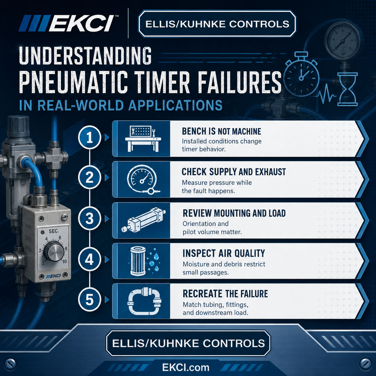
A pneumatic timer valve can pass a bench check because the test line is short, clean, and supplied by stable shop air. Once installed, the same timer may see lower pressure at its inlet than the regulator gauge indicates. The useful reading is not only main line pressure. Measure pressure as close as possible to the timer port while the machine is cycling.
Small restrictions can also change timer behavior. Long tubing runs, undersized push-to-connect fittings, kinked lines, clogged silencers, and restricted exhausts can change the delay or prevent the timer pneumatic valve from completing its function. A timer may look defective when it is being starved, back-pressured, or affected by another device pulling air from the same branch.
Measure pressure while the fault is happening, not only at rest. Inspect elbows, manifolds, mufflers, needle valves, and quick fittings for hidden restrictions. Confirm exhaust air can leave freely and is not trapped by a blocked silencer. Check whether other valves or actuators cycle at the same moment and create a temporary pressure sag.
Check Mounting Position and Connected Circuit Load
A pneumatic timer can behave differently once its body, ports, and adjustment mechanism are installed in the actual panel or machine frame. Orientation may alter drain paths, knob access, mechanical stress on fittings, or how vibration reaches the timer pneumatic valve. A bench setup rarely duplicates the same bracket tension, hose routing, or movement transferred from nearby equipment.
The installed pneumatic time-delay valve may also be working against a larger controlled volume than it encountered during a quick bench check. Long pilot lines, additional chambers, or connected valve operators can change the moment when the delayed signal becomes useful to the machine. The timer may complete its internal delay, yet the connected device may still respond late, weakly, or not at all.
A pneumatic timer circuit can appear healthy when the pneumatic timer delay switch is tested alone, and then fail when several devices depend on the same timed signal. Pilot-operated valves, safety interlocks, sequence valves, and cylinder controls may all add demand that was absent on the bench. The result can look like a defective pneumatic delay timer even when the installed circuit is the real variable.
Verify the timer is mounted in the intended orientation. Confirm no fitting torque is distorting the body or ports. Compare the bench load to the actual connected pilot devices. Check whether interlocks must shift before the timed output can act. Isolate downstream devices one at a time when safe to identify excessive demand.
| Installed issue | What to check | Why it matters |
| Lower pressure at the timer | Measure at the timer inlet during machine motion | The regulator may show normal pressure while the timer sees a pressure drop |
| Restricted exhaust | Inspect mufflers, silencers, exhaust ports, and fittings | A timer may not reset cleanly if air cannot leave the circuit |
| Larger downstream volume | Compare bench load to pilot lines, chambers, and valve operators | More volume can delay or weaken the timed output |
| Added actuator or valve demand | Isolate connected devices when safe | The timer may work alone but fail when several devices depend on the same signal |
| Mounting stress or vibration | Check orientation, bracket tension, tubing pull, and nearby machine movement | The installed position can change timer response even when the device passes a bench test |
Check Air Quality and Machine Environment
A clean bench setup can hide air-quality problems that only reach the pneumatic timer after installation. Moisture, oil carryover, particulates, and seal debris can accumulate within small passages and restrictors, thereby restricting flow. Those contaminants can change how the pneumatic delay timer fills, vents, or shifts. A timer pneumatic valve may cycle normally in open air, and then become sluggish or inconsistent once connected to dirty plant lines.
The surrounding environment can create the same false failure pattern. Vibration may disturb marginal internal movement, temperature swings can alter seal friction, and cabinet heat can change response after the machine has been running. Washdown areas add another risk because intermittent moisture may not be present during a quick bench check but can appear during production.
Inspect filters, drains, lubricators, and upstream regulators. Crack open safe drain points to check for water or discoloration. Look for residue at ports, fittings, mufflers, and exhaust vents. Replace clogged silencers or restrictors before condemning the timer. Note whether failures occur after washdown, startup, long runtime, or temperature change.
Recreate Machine Conditions before Replacing the Timer
A reliable diagnosis starts by making the test conditions match the machine conditions. If pneumatic timers pass on a clean bench setup but misfire in production, the difference is usually in the circuit around the device rather than the device alone. Record values at the timer ports while the machine is cycling, not only at the main regulator.
The goal is to replicate the real installation closely enough that the failure can be reproduced. Keep the same tubing run, fittings, downstream volume, and mounting angle whenever practical. Cycle nearby valves and actuators simultaneously so the pneumatic timer sees the same demand pattern it does during production.
Measure inlet pressure before actuation, during actuation, and at the moment timing should complete. Compare the delay time with the timer disconnected from the machine load, then reconnected. Verify whether the timer pneumatic valve shifts cleanly when downstream devices are attached. Mark whether the fault appears during startup, rapid cycling, idle restart, or extended runtime.
Partner with Ellis/Kuhnke Controls Before You Replace the Timer
A pneumatic timer that passes on the bench but fails in the machine is often reacting to the installed circuit rather than proving itself defective. Pressure drop, restricted flow, exhaust blockage, downstream load, mounting position, contamination, vibration, and heat can all affect timing behavior once the device returns to production. The real diagnosis starts by comparing bench conditions to machine conditions and identifying what changed. Replacing the timer too early can leave the root cause in place, leading to the same failure recurring. Before ordering another pneumatic timer valve, record the timer model, circuit layout, air pressure readings, mounting position, machine conditions, and symptom pattern. Partner with Ellis/Kuhnke Controls to review the application, isolate the likely cause, and choose the right next step.
Related Reading
- What Are Pneumatic Controls, and How Do You Choose or Use Them Correctly?
- How to Choose a Pneumatic Indicator without Creating False Status
- How to Optimize Pneumatic Control Systems with the Right Timers
- Pneumatic Timers: How to Select the Right Model for Your Circuit
- Basic Principles of Pneumatic Control Systems


- Ellis/Kuhnke Controls
132 Lewis Street Unit A-2, Eatontown, N.J. 07724
Phone: 1-800-221-0714
Fax: 732-291-8154
Email: Info@ekci.com
- Home Pneumatic Controls Technical Info CAD Drawings Contact Us Pneumatic Timers Blog Site Map