How to Choose a Pneumatic Indicator without Creating False Status

A pneumatic indicator should not be chosen because it fits the panel hole or shows the right color. It should be chosen because it proves the exact pneumatic condition the machine, operator, or technician needs to see. When that condition is vague, the indicator can make a healthy circuit look failed or a failed circuit look ready.
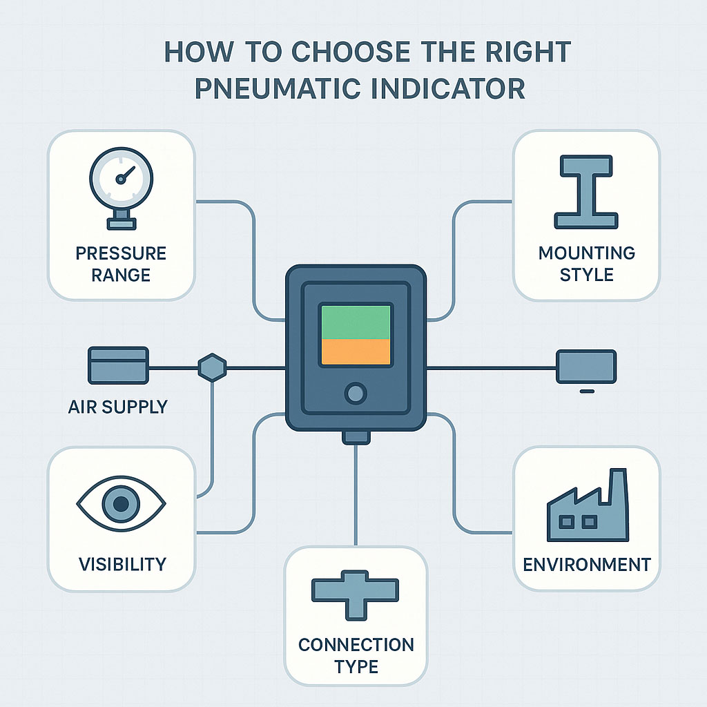
That false status matters on a production floor. It can send maintenance teams to the wrong problem, delay startup, hide an air-supply issue, or create confidence in a replacement part that fits physically but does not confirm the required circuit condition. The right selection process starts with function, and then moves to pressure or flow range, interface, media, environment, visibility, and replacement fit.
Start with the Condition the Circuit Must Prove
A pneumatic indicator confirms a local condition. It might show pressure, threshold pressure, flow, valve signal state, cylinder position, or another air signal. The first decision is not color, window style, thread size, or brand. The first decision is the specific condition the indicator must prove in the circuit.
That question should be answered in machine language, not appearance language. "Red indicator on the panel" does not provide maintenance or purchasing with enough information. A better description would say "shows pilot pressure to the clamp valve," "confirms regulated air is above the minimum setpoint," or "shows exhaust flow during release." Once the function is clear, the remaining specifications have a real target.
- Pressure present:The indicator proves air pressure exists at a point. It does not prove useful flow or machine movement.
- Pressure above threshold:The indicator proves pressure reached a set actuation level. It does not prove downstream motion occurred.
- Flow present:The indicator proves air is moving through a path. It does not prove pressure alone is adequate.
- Valve signal state:The indicator indicates whether a pilot signal or pneumatic command has reached a valve. It does not prove supply pressure reached every circuit section.
- Cylinder position:The indicator proves an actuator reached or left a position. It does not prove port pressure equals completed travel.
This distinction keeps the part tied to the job it performs. A pressure indicator, a flow indicator, and a position-related indicator do not answer the same question. Treating them as interchangeable visual accessories is the point where false status usually enters the machine.
Avoid Readings That Look Clear but Mean the Wrong Thing
A clear visual change is only useful when it represents the right pneumatic condition. A mismatch in function, range, connection, media, or location can create a false positive or a missed indication. The result is a part that appears helpful but gives operators or technicians the wrong basis for action.
A pressure presence indicator installed upstream of a blocked passage can show that air is available while the actuator receives no usable air. A threshold indicator with the wrong actuation point can show "ready" at a pressure below the threshold for reliable clamping. A flow indicator installed in the wrong direction or outside its flow range can appear inactive even when part of the circuit still operates.
- Under-rated pressure range:The device may leak, stick, fail early, or show unreliable status because it is working outside its rating.
- Wrong actuation condition:The indicator may show pressure presence when the real requirement is threshold pressure, flow, or position.
- Incorrect port or interface:Poor sealing, poor alignment, adapters, and rework can change fit, clearance, or response.
- Media mismatch:Seal, window, or moving-element damage can shorten service life or make the indication hard to trust.
- Poor visibility:The indicator can be installed correctly but still fail its purpose if the person who needs it cannot read it from the normal position.
- Unsuitable environment:Heat, dust, oil mist, washdown, vibration, UV, or impact can cause sticking, clouding, breakage, or unreadable status.
Pressure and temperature limits should comply with the manufacturer's rating and the machine's pneumatic safety basis. ISO 4414 is a common reference for pneumatic fluid power system safety, and compressed-air quality is commonly classified under ISO 8573. Visual indication also does not replace required sensing, alarms, interlocks, or lockout procedures. Pneumatic energy can remain in one part of a system even when another section appears vented, so hazardous-energy control still needs to follow OSHA's guidance on hazardous energy control.
Use the Indicator Type That Matches the Circuit Question
Different indicator styles answer different circuit questions. Selection gets easier when the part type is tied to the status the machine needs to show. This also helps purchasing teams avoid matching a replacement by face color or thread alone.
A pressure presence indicator is often the simplest visual device. It is useful at regulators, supply branches, valve islands, and local machine panels where maintenance personnel need to know whether air is present. It should be rated for the normal and maximum pressure at that location. It should not be used as proof that pressure is high enough for the process unless the device is designed to indicate a threshold condition.
A threshold indicator is more specific. It is selected around an actuation pressure, reset behavior, and maximum pressure rating. This style helps when the machine needs visual confirmation that pressure has reached a practical operating level, such as the minimum clamp pressure or the minimum supply pressure to a pneumatic control circuit. If the process requires 70 psi and the indicator actuates at 30 psi, it can show ready before the circuit is ready.
A flow indicator is used when air movement matters. A line can be pressurized with little or no meaningful flow if a valve is closed, a passage is blocked, or a downstream component has not shifted. Flow indicators should be matched to expected flow range, pressure drop, port size, direction, contamination tolerance, and whether the flow is continuous, intermittent, supply, or exhaust.
A pilot signal indicator helps separate command status from main circuit response. It can indicate that a pneumatic command reached a directional valve, an actuator control valve, or another air-operated device. That is useful for troubleshooting, but it does not prove that the main valve shifted correctly, that downstream pressure reached the actuator, or that the actuator completed its stroke.
A position-related indicator is tied to movement or mechanical state. Depending on the design, it may show valve position, cylinder position, or a related pneumatic or mechanical condition. These indicators are useful where the desired status is not simply air pressure but whether a device reached, left, or passed a position. Selection depends on mounting geometry, travel reference, actuation method, visibility, and environmental exposure.
Match the Indicator to the Application before Ordering
The fastest way to avoid a bad selection is to connect each ordering detail to the circuit function. A part that works on a dry, regulated panel line may fail or mislead on a lubricated, high-vibration machine section. A part that is easy to read at eye level may be useless inside a cabinet, behind guarding, or from the operator's normal approach direction.
|
Selection Question |
Best Indicator Focus |
Verify Before Ordering |
|
Need proof that pressure exists? |
Pressure presence or signal indicator |
Operating pressure, port, thread, visibility, media |
|
Need proof that pressure reached a usable level? |
Threshold-style indicator |
Actuation pressure, reset behavior, maximum pressure, orientation |
|
Need proof that air is moving? |
Flow indicator |
Flow range, pressure drop, tubing interface, contamination tolerance |
|
Need proof of a pilot signal or valve state? |
Pneumatic signal indicator |
Pilot pressure, response condition, port, panel location |
|
Need proof of actuator position? |
Position-related indicator |
Actuation method, mounting fit, travel reference, visibility, environment |
For B2B maintenance, engineering, and purchasing teams, the best ordering description includes both the physical part attributes and the function it supports. That prevents a replacement from being treated as suitable simply because it fits the same hole. The question is not only “Will it install?” The better question is “Will it prove the same condition at the same point in the circuit?”
Check the Details That Change the Reading
Small specification differences can change what the indicator seems to prove. Before treating a part as suitable, check the exact installation point and the condition the device must confirm. These details matter most when the part is used for troubleshooting, setup, startup checks, or operator-visible status.
- Signal condition:Confirm whether the indicator must show pressure, threshold, flow, valve signal, cylinder position, or another air signal.
- Normal range:Confirm the daily pressure or flow the indicator must handle during normal operation.
- Maximum range:Account for startup spikes, regulator drift, upstream variation, and the highest pressure the part will see.
- Interface:Check port size, thread type, tube size, fitting style, panel hole, manifold fit, cabinet location, and orientation.
- Media:Match the device to filtered air, lubricated air, moisture, oil mist, particulates, or non-standard gases.
- Environment: Check heat, washdown, dust, oil mist, vibration, impact, outdoor exposure, and UV exposure.
- Visibility:Confirm color, contrast, viewing angle, lighting, label space, and the position of the person reading it.
- Replacement fit:Measure body size, panel thickness, depth, locknut clearance, fitting orientation, markings, and actuation condition.
This check should occur before the part number is considered final. It is also useful when the existing indicator failed, because the failure may reveal a selection problem. A cloudy window, a cracked body, a sticking mechanism, or a faded face can point to media or environmental exposure that the replacement needs to handle better.
Choose the Part That Makes the Machine Easier to Trust
A good pneumatic indicator reduces uncertainty at the machine. It tells the operator, technician, or maintenance planner what condition exists at a specific point in the circuit. That value disappears when the indicator is selected as a general visual accessory instead of a circuit-specific status device.
The safest selection path is direct. Define the condition first. Match the indicator type to that condition. Verify range, media, interface, visibility, environment, and replacement fit. When those details line up, the indicator does more than change color or move. It gives the team a status they can use without having to guess what the circuit is really doing.
Related Reading


- Ellis/Kuhnke Controls
132 Lewis Street Unit A-2, Eatontown, N.J. 07724
Phone: 1-800-221-0714
Fax: 732-291-8154
Email: Info@ekci.com
- Home Pneumatic Controls Technical Info CAD Drawings Contact Us Pneumatic Timers Blog Site Map