
Pneumatic Controls: What Should You Check When a Valve, Timer, and Pressure Signal Do Not Agree?
A pneumatic fault rarely appears as one clearly failed part. More often, it appears as a disagreement between the commanded event, the valve’s physical response, the timer output, and the pressure signal. In pneumatic controls, that mismatch can make a good solenoid look bad, make a timer seem unreliable, or make a pressure switch look out of calibration. The practical path is to isolate the sequence in order and then compare the evidence gathered under the same operating conditions.
Verify the Commanded Event before Condemning the Valve
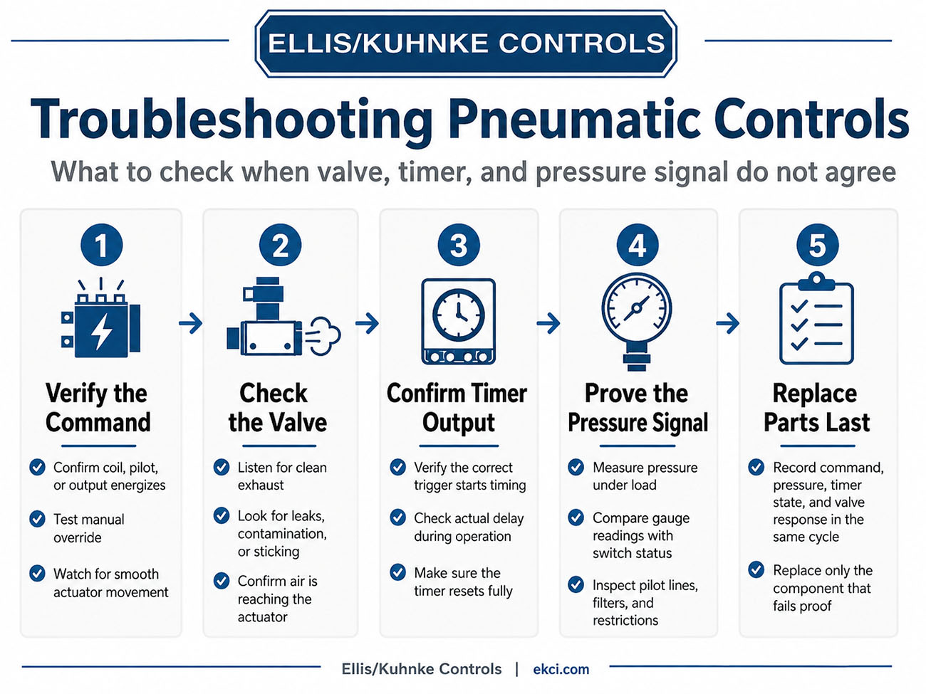
Start by separating the command from the valve body’s mechanical action. A coil light, PLC output, or pilot indication proves that a command was attempted, but it does not prove that the spool shifted or that air reached the actuator. When the machine design allows it, compare normal operation with the valve’s manual override. If the actuator moves correctly with the override but not with the command, the fault is more likely in the signal path than in the valve body.
- Correct coil, pilot port, or output energizes for the intended motion.
- Manual override shifts and returns or detents as designed.
- Exhaust sound changes cleanly without muffling or constant leakage.
- Actuator motion is smooth, complete, and in the expected direction.
A valve that receives the right command should not be replaced until the air path is proven. Spool movement can be slowed by debris, swollen seals, moisture, varnish, or contamination that appears only after idle periods. Exhaust restrictions are especially easy to miss because supply pressure may look normal while trapped air delays return motion. Silencers, flow controls, quick-exhaust valves, and kinked tubing can all make a healthy valve appear sluggish.
The next check is whether pressure and flow leaving the valve match the actuator’s behavior. Leaking fittings, cracked tubing, worn cylinder seals, or a misadjusted speed control can bleed energy after the valve has already shifted. The strongest diagnosis compares the command, valve shift, exhaust event, and actuator stroke during the same cycle. That keeps the fault path grounded in observed behavior rather than the most visible component.
Confirm the Timer Output and Sequence
When valve response and pressure feedback do not line up, the timer is often blamed too quickly. The timer should be treated as a sequencing device, not only as a dial with a number on it. First, confirm what event is supposed to start timing, such as a solenoid energizing, a limit valve changing state, a pressure switch proving force, or a PLC output enabling the next step. If the timer starts from the wrong trigger, the delay can be accurate and still appear wrong in the machine cycle.
- Start signal arrives once, not repeatedly or intermittently.
- Actual delay matches the required cycle time while running.
- Timer resets fully before the next cycle begins.
- Permissive signals are not blocking the output.
The timer output should be checked at the actual terminal or port. An indicator light may confirm that the timing circuit is energized, but it may not prove that the output contact, pilot signal, or downstream device is receiving a usable command. A setting that appears correct on the faceplate can still be wrong because of vibration, scale mismatch, aging components, or an undocumented adjustment. The sequence should be traced in the order: trigger, timing interval, reset state, output, and downstream response.
A timer can appear faulty when the surrounding conditions are incomplete. A pressure signal may arrive late because a cylinder is moving slowly, an exhaust path is restricted, or a regulator is set too low for the load. In that case, the timer may be waiting correctly while the rest of the circuit fails to satisfy the next step. Proving the timer output prevents a sequencing delay from being mistaken for a timing failure.
Prove the Pressure Signal and Sensing Path
When the valve and timer appear to disagree, the pressure signal connects control logic to physical reality. A pressure switch, transducer, or pilot signal may report “made” or “not made,” but that indication matters only if the sensing point reflects the condition the sequence depends on. Header pressure at the source does not guarantee that the actuator, pilot branch, or switch port is seeing the same value under load. Pressure must be compared at the point where the circuit is supplied and at the point where the signal is sensed.
- Supply pressure holds under load, not only at idle.
- Regulator settings match required pilot and actuator pressures.
- Filters, bowls, drains, and restrictions are clear.
- Gauge readings agree with switch or transducer status.
The sensing path deserves as much attention as the device at its end. Small pilot lines can kink, collect oil or condensate, trap debris at fittings, or become restricted enough to delay a pressure switch while the main circuit appears normal. Leaks can create the opposite problem, in which pressure rises high enough to briefly satisfy a device, then falls before the timer or valve completes the next action. Slow buildup and slow bleed-off often make the fault appear intermittent, especially when the sequence works at one cycle rate but fails as demand increases.
A failed pressure switch remains possible, but it should be proven rather than assumed. Applying a known pressure at a test port can separate the device response from the circuit condition. If the switch repeats accurately, attention returns to the pneumatic path that feeds it. If it switches late, chatters, or fails to reset during bleed-off, the component may be the root cause rather than a symptom.
Compare the Evidence before Replacing Parts
A pneumatic controls fault is best solved by proving where the sequence stops matching reality. The commanded event should match valve movement, the timer output should match the intended sequence, and the pressure signal should be present, stable, and arriving at the correct point in the cycle. When those checks are documented together, the disagreement becomes a traceable chain of cause and effect.
|
Evidence |
Agreement |
Mismatch Suggests |
|
Command state |
Correct output activates at the expected step |
Wiring, PLC, pilot supply, or trigger issue |
|
Valve response |
Spool shifts, exhaust changes, actuator moves |
Sticking valve, restriction, leakage, or blocked exhaust |
|
Timer condition |
Trigger, delay, reset, and output match sequence |
Wrong trigger, missed reset, blocked permissive, or timer fault |
|
Pressure signal |
Gauge pressure and device status change together |
Restriction, leak, low regulation, or faulty sensing device |
Replacing the most accessible part rarely fixes an out-of-sequence circuit. Replacing the component that has been proven unable to switch, reset, pass air, or report pressure protects uptime and maintenance budgets. Before a replacement order is written, the command state, measured pressure, timer condition, valve response, and reset behavior should be recorded under the same operating conditions. If the readings still do not align, Ellis/Kuhnke Controls can help determine whether the issue lies with the valve, timing element, signal path, or circuit design.
Related Reading
- How Do You Troubleshoot Pneumatic Controls When a Machine Cycles Out of Sequence?
- What Are Pneumatic Controls, and How Do You Choose or Use Them Correctly?
- How to Choose a Pneumatic Indicator without Creating False Status
- How to Optimize Pneumatic Control Systems with the Right Timers
- Pneumatic Timers: How to Select the Right Model for Your Circuit


- Ellis/Kuhnke Controls
132 Lewis Street Unit A-2, Eatontown, N.J. 07724
Phone: 1-800-221-0714
Fax: 732-291-8154
Email: Info@ekci.com
- Home Pneumatic Controls Technical Info CAD Drawings Contact Us Pneumatic Timers Blog Site Map