
Why Use Pneumatic Controls Instead of Explosion-Proof Cabinets?
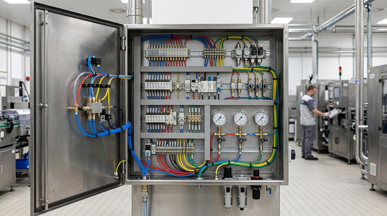
Explosive Atmosphere Automation and Fluid Power Logic Architecture
In facilities where flammable vapors or combustible dust may be present, machine controls cannot be treated like ordinary electrical equipment. Even a small electrical fault or ignition source can create a serious hazard, which makes automation more complicated for plant managers and process engineers working in Class I, Division 1, Zone 0, and other classified environments. The challenge is not simply automating the equipment. It is doing so without introducing unnecessary electrical risk into the hazardous area.
Pneumatic controls provide a direct way to reduce that risk by using compressed air instead of electricity to perform machine control functions. For suitable applications, an all-pneumatic system can reduce reliance on explosion-proof electrical hardware while still providing the sequencing and control needed to operate industrial machinery. Where electrical ignition risk is a primary concern, pneumatic control architecture can offer a simpler and safer approach to hazardous-area automation.
Fluidic Mechanics and Boolean Logic Signal Processing Architecture
The physical operation of moving-part pneumatic logic systems is governed by fluid dynamics and classical pneumatic mechanics. Unlike digital microprocessors that transmit information through electron flow across silicon semiconductors, pneumatic logic systems process signals using differential pressure waves transmitted through flexible tubing. Miniaturized spool valves, elastomeric diaphragm poppets, and shuttle elements act as fluidic transistors, switching states rapidly based on pilot pressure thresholds.
Moving-part logic elements execute standardized Boolean algebraic functions entirely through physical air pressure. A pneumatic AND gate incorporates a dual-pressure shuttle spool that requires simultaneous pilot signals from two independent input ports before delivering an output pressure signal. Pneumatic OR gates utilize floating shuttle elements that allow either of two distinct pilot lines to trigger machine actuation without permitting back-leakage into the inactive supply line.
Furthermore, pneumatic NOT gates function as continuous inverters, maintaining steady output pressure until an incoming pilot signal closes the primary orifice and vents downstream pressure to atmosphere. Integrated air-delay timers combine miniature variable needle orifices with calibrated fluidic accumulator volumes, delivering precise, repeatable delay intervals from 0.5 seconds to several minutes. These modular logic components mount directly to standardized manifold sub-bases, enabling complex sequential automation cycles without a single milliwatt of electrical current.
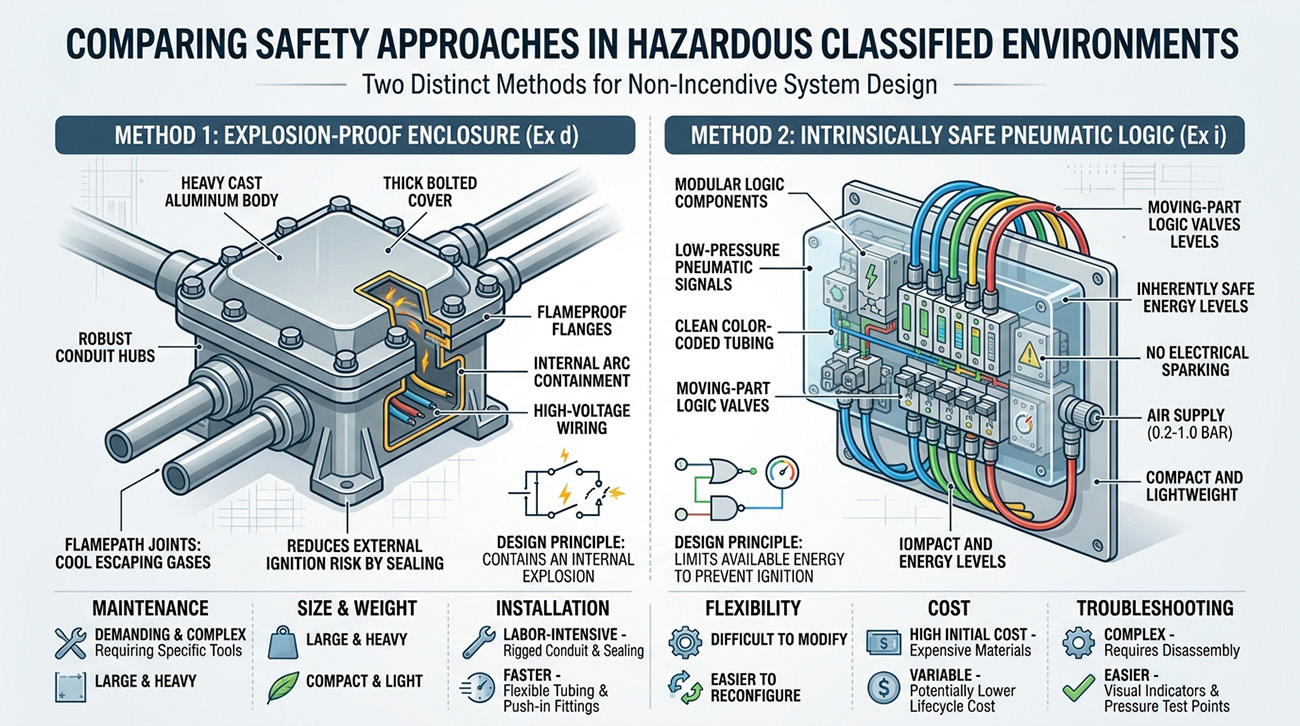
Why Electronic Solenoids and NEMA 7 Explosion-Proof Enclosures Fail in Harsh Plants
Plant automation engineers accustomed to general-purpose manufacturing frequently assume that packaging standard electrical controls inside heavy explosion-proof enclosures represents the best approach. Relying on electronic solenoids and heavy cast-iron NEMA 7 or NEMA 9 enclosures introduces severe financial, operational, and maintenance liabilities.
Electronic explosion-proof hardware presents three fundamental failure vectors in hazardous chemical environments.
- Extravagant Capital and Conduit Sealing Expenses: Cast-iron explosion-proof enclosures, explosion-proof conduit fittings, and poured sealing compounds increase automation installation costs by 300% to 500% compared to standard industrial panels and complicate future line modifications.
- Thermal Hotspot Ignition from Continuous Solenoid Cycling: Electrical solenoid coils continuously generate inductive heat during automated cycling; in dusty operating areas, heat trapped inside sealed enclosures can exceed the auto-ignition temperature of ambient chemical vapors.
- Corrosive Vapor Infiltration and PCB Delamination: Harsh chemical fumes and caustic washdown sprays penetrate enclosure gasket seals over time, corroding terminal blocks, degrading copper traces, and causing premature printed circuit board short circuits.
Attempting to mitigate electronic failure through frequent gasket replacements and certified hot-work maintenance permits creates persistent production bottlenecks. In contrast, fluidic logic elements operate cold, produce zero electrical heat, and cannot generate a spark under any physical failure mode. By adopting all-pneumatic automation systems, plant managers eliminate regulatory burdens and thermal ignition risks.
Sub-Base Manifold Engineering, Positive Pressure Purging, and Air Preparation
Industrial pneumatic control panels achieve high operational density through engineered multi-station sub-base manifolds. Miniature logic elements, spool valves, and pressure regulators plug directly into precision-ported aluminum or composite manifold blocks mounted on standard 35 mm DIN rails. Internal manifold porting routes primary supply pressure and common exhaust paths internally, slashing external tubing connections by over 70% and eliminating installation clutter.
An inherent operational advantage of pneumatic logic systems is continuous outward positive-pressure purging. As pneumatic valves cycle, clean, filtered exhaust air vents continuously through sintered bronze mufflers inside the control cabinet. This outward airflow maintains a slight positive pressure barrier inside the enclosure, preventing acidic chemical fumes, airborne dust particulates, and humid washdown vapors from entering the cabinet.
Ensuring multi-million-cycle reliability requires adhering to standardized compressed air preparation protocols. Inlet plant air must pass through high-efficiency coalescing particulate filters, precision pressure regulators, and desiccant dryers compliant with ISO 8573-1 Class 1.4.1 cleanliness criteria. Delivering clean, dry air free of liquid water and compressor oil droplets guarantees that moving-part logic spools operate with near-zero friction across decades of round-the-clock production.
Comparative Analysis of Hazardous Location Automation Architectures
|
Control Architecture |
Ignition Hazard Level |
Installation Capital & Labor Cost |
Chemical & Washdown Resilience |
OSHA & NEC Recertification Burden |
|
All-Pneumatic Logic Control Systems |
Inherently zero spark; 100% explosion-proof |
Low; standard tubing & modular sub-bases |
Exceptional; brass & Viton construction |
Zero hazardous electrical audit burden |
|
NEMA 7/9 Explosion-Proof Electrical Panels |
Explosion-containment design (External hot arcs) |
Extremely high; heavy cast-iron boxes & seals |
Moderate; corrosive fumes degrade copper wires |
Severe; requires certified re-inspection after edits |
|
Intrinsically Safe Zener Barrier Systems |
Low electrical energy (Milliamp limiting) |
High; costly isolated barrier modules & wiring |
Poor; sensitive electronics vulnerable to moisture |
High; strict circuit capacitance calculation rules |
|
Purged & Pressurized Type X Cabinets |
Relies on continuous protective gas purging |
Very high; complex interlocks & purge timers |
Moderate; purge failure triggers immediate shutdown |
Substantial; requires annual flow & pressure checks |
|
Standard General-Purpose Electronics |
Fatal ignition hazard; strictly prohibited |
Low capital cost; catastrophic hazard risk |
Fails rapidly in corrosive chemical washdown |
Violates federal OSHA and NEC safety mandates |
Diagnostic Field Inspection Protocol for Hazardous Pneumatic Logic Circuits
Maintaining flawless automation performance in classified hazardous locations requires systematic diagnostic testing during commissioning and routine maintenance. Because pneumatic systems operate without electrical currents, technicians troubleshoot circuits safely using mechanical gauges and visual indicators.
A standardized pneumatic logic diagnostic protocol incorporates three essential mechanical checks:
- Pilot Pressure Differential Gauge Calibration: Calibrated digital test gauges measure supply and pilot signal pressures across logic valves, confirming that switching pilot pressures meet manufacturer-specified activation thresholds.
- Manifold Inter-Port Bubble Leak Testing: Sub-base manifold channels undergo ultrasonic and bubble leak inspections under static 90 psi air pressure, verifying that inter-port seals prevent parasitic pressure bleed between logic gates.
- Exhaust Backpressure and Dynamic Response Timing: Precision flow sensors monitor exhaust port flow restrictions, confirming that muffler backpressure does not exceed 2 psi and ensuring cycle response times remain under 20 milliseconds.
Systematic pneumatic diagnostics ensure automated processing machinery operates with clockwork repeatability. Documenting inspection results provides complete compliance verification for plant safety managers and environmental health inspectors. Properly maintained pneumatic circuits deliver safe, uninterrupted automation across severe hazardous chemical environments.
Intrinsically Safe Machine Automation with Ellis Kuhnke Controls
Eliminating explosion risks in volatile chemical processing zones requires moving beyond cumbersome explosion-proof electrical enclosures toward intrinsically safe pneumatic logic. By executing complex machine automation sequences through compressed air, process facilities achieve total spark-free safety while drastically lowering installation and maintenance expenses. Inherent positive-pressure purging, extreme chemical resilience, and straightforward mechanical diagnostics make pneumatic logic the premier choice for hazardous area automation.
Ellis Kuhnke Controls is a recognized global pioneer in fluid power automation, engineering advanced moving-part pneumatic logic, directional control valves, and custom sub-base assemblies for hazardous industrial environments. With decades of technical application expertise, we design and build turnkey pneumatic control panels tailored specifically to customer machine specifications. To review hazardous location automation schematics, evaluate custom sub-base manifold designs, and implement spark-free pneumatic logic, contact Ellis Kuhnke Controls at (800) 221-0714.
Related Reading
- Pneumatic Controls: What Should You Check When a Valve, Timer, and Pressure Signal Do Not Agree?
- Understanding Pneumatic Timer Failures in Real-world Applications
- How Do You Troubleshoot Pneumatic Controls When a Machine Cycles Out of Sequence?
- What Are Pneumatic Controls, and How Do You Choose or Use Them Correctly?
- How to Choose a Pneumatic Indicator without Creating False Status


- Ellis/Kuhnke Controls
132 Lewis Street Unit A-2, Eatontown, N.J. 07724
Phone: 1-800-221-0714
Fax: 732-291-8154
Email: Info@ekci.com
- Home Pneumatic Controls Technical Info CAD Drawings Contact Us Pneumatic Timers Blog Site Map