
Why Pneumatic Controls Work One Cycle and Stall the Next
Why Pneumatic Controls Work One Cycle and Stall the Next
Few maintenance headaches on an automated industrial line are more frustrating than an intermittent sequence stall. A cylinder advances normally for several cycles, then stops before reaching the position that should trigger the next step. Restarting the machine may make it run again, but that does not establish that the valve, timer, or actuator is sound. It only tells you that the failure is not present under every operating condition.
At Ellis/Kuhnke Controls, we recommend describing the failed transition before choosing replacement pneumatic controls. Which movement or signal should have occurred, and what actually happened instead? The answer helps separate a missing input, a component that did not respond, and a mechanical movement that did not finish. Replacing a part simply because it is near the stalled step can leave the actual problem in place.
Troubleshooting must be performed by qualified personnel using the machine manufacturer's procedures. Before servicing, isolate and control hazardous energy, including stored pneumatic energy, and verify the safe condition. Live diagnostic observations require an authorized procedure and safeguards. Do not bypass interlocks, force a sequence, or treat an emergency-stop reset as a repair.
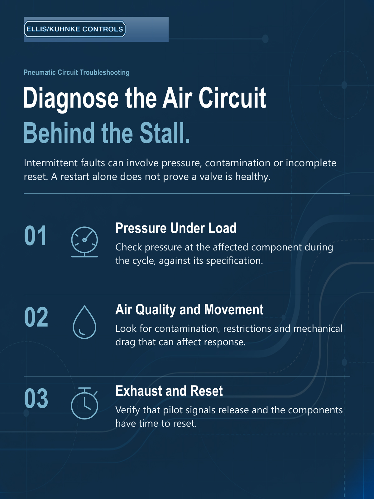
Record the first thing that did not happen
A machine that stops on step three may have a problem that began during step two. If the preceding cylinder did not reach its intended position, the next valve may never receive the signal it needs. The stationary valve is then an observation, not yet the cause. A useful fault record distinguishes what was commanded, what moved, and which indication or signal was missing.
Compare a successful cycle with the failed one using information that can be gathered safely under the approved procedure. Note whether the fault follows a long idle period, occurs during other equipment's air demand, or appears after a recent component or tubing change. Those patterns are clues, not proof. A morning-only problem, for example, does not establish contamination as the cause without further evidence.
Give the technician or supplier concrete information:
- The machine step and component identification at the point of failure.
- The expected input, output, and movement according to the circuit documentation.
- Whether the previous operation completed and its confirmation signal occurred.
- Relevant pressure observations, recent changes, and the conditions under which the fault repeats.
A normal idle gauge does not settle the pressure question
The wall gauge may look normal while the machine is stopped. That reading does not establish what pressure is available at the relevant component when the circuit demands flow. Restrictions, supply conditions, and simultaneous demand can change the operating situation. The useful comparison is with the component's requirements at the point and time relevant to the failed step.
Do not substitute a universal minimum pressure for the actual data sheet. Different valves and control elements have different operating requirements. Nor should the response be to increase pressure until the machine appears to work. A change can conceal the fault or exceed another component's limits. Qualified personnel should identify the cause and remain within the approved system specifications.
Check the return path as well as the incoming signal
Pneumatic operation involves both supplying air and allowing it to exhaust as required by the circuit. A restricted exhaust path can affect movement or reset behavior. In some circuits, a signal that has not cleared can also interfere with the next intended operation. The circuit diagram and component function determine what should happen; there is no single reset explanation that fits every pneumatic control.
For example, a technician may observe that the first cycle after a long pause succeeds while rapid successive cycles do not. That makes reset conditions and timing worth investigating, alongside other possible causes. It does not justify removing a muffler, changing tubing, or forcing a valve while the equipment is operating. Any inspection or adjustment must follow the authorized maintenance procedure.
|
Observed pattern |
Question to investigate |
|
Failure during high air demand |
Does the relevant component receive the required operating conditions during the failed step? |
|
Next cycle begins before the previous state clears |
Does the documented sequence allow the required reset and exhaust conditions? |
|
Actuator stops short of its intended position |
Is mechanical resistance, loading, or another fault preventing the confirmation signal? |
|
Trouble began after a substitution |
Do the new component's function and requirements match the approved circuit? |
Keep component faults in the investigation
Contamination, wear, damaged seals, and mechanical binding remain possible causes. A restart does not rule them out. At the same time, installing a new component into an unresolved supply or contamination problem may not produce a lasting correction. Inspect and evaluate against the manufacturer's instructions rather than decide in advance that either the component or the air supply must be responsible.
Once a cause is supported, document the corrective action and verify operation under the conditions that previously produced the stall. A successful single cycle is weak evidence for an intermittent problem. The responsible maintenance team should determine an appropriate verification procedure and restore all required safeguards before return to service.
Replace the part only after the fault description makes sense
Pneumatic controls can work one cycle and stall the next because their inputs, pressure, exhaust, reset, mechanical load, or condition are not the same at each operation. The solution is to identify the failed transition and check the relevant requirements, not to assume a reset proves the hardware is healthy.
Contact Ellis/Kuhnke Controls with the component number, pneumatic schematic, expected sequence, and the observations recorded by your qualified technician. We can discuss component requirements and available replacement options. That gives the selection conversation a defined problem to address instead of another round of speculative part swapping.
Related Reading
- Why Use Pneumatic Controls Instead of Explosion-Proof Cabinets?
- Pneumatic Timers: What Should You Confirm Before Replacing a Timing Unit?
- Pneumatic Controls: What Should You Check When a Valve, Timer, and Pressure Signal Do Not Agree?
- Understanding Pneumatic Timer Failures in Real-world Applications
- How Do You Troubleshoot Pneumatic Controls When a Machine Cycles Out of Sequence?


- Ellis/Kuhnke Controls
132 Lewis Street Unit A-2, Eatontown, N.J. 07724
Phone: 1-800-221-0714
Fax: 732-291-8154
Email: Info@ekci.com
- Home Pneumatic Controls Technical Info CAD Drawings Contact Us Pneumatic Timers Blog Site Map