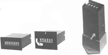
Understanding how a Pneumatic Timer Works
It is not uncommon to find pneumatic timers being used in environments where electrical currents are present. Other systems, like electrical or fossil fuels, can be dangerous in areas that have electricity. For instance, an oil refinery will use pneumatic valves and timers instead of their electrical counterparts. A small spark from an electrical timer could lead to catastrophic problems.
How a pneumatic timer works may be slightly confusing, but in many cases, the devices are basic. The most straightforward timer only uses a control valve and piston. Of course, all pneumatic equipment must be attached to a working air supply. Without one, no pneumatic device could work.
The devices work when air slowly pushes the piston in the direction towards the end of the chamber. On the other side is a valve that is needed to control the flow of air. Pistions will work until they have ended at the intended destination; however, the position will take time to complete its task. Other air timers are available, and they use different controlling mechanisms (piston chamber is most popular).

Pneumatic Timers
For more information about picking and purchasing pneumatic timers, let us be your first call.
Pneumatic Controls
- Basic Principles of Pneumatic Controls
It is common for a pneumatic control system to be designed in the form of a pneumatic circuit. The circuits are formed using various components, such as pneumatic cylinders and pneumatic valves.
- Three Reasons to Consider Pneumatic Valves
- Getting a Handle of Your Pneumatic Flow Controls


- Ellis/Kuhnke Controls
132 Lewis Street Unit A-2, Eatontown, N.J. 07724
Phone: 1-800-221-0714
Fax: 732-291-8154
Email: Info@ekci.com
- Home Pneumatic Controls Technical Info CAD Drawings Contact Us Pneumatic Timers Blog Site Map
