Basic Principles of Pneumatic Control Systems
Pneumatic control systems usually get attention only after something goes wrong. A machine starts cycling out of order, a delay disappears, or a valve shifts too early, and no one can trace why. The frustrating part is that everything looks simple on the surface, just air, tubing, and a few components, but the behavior does not match what the system is supposed to do. That gap between expected performance and actual output is where operators, engineers, and maintenance teams lose time.
At its core, the question is straightforward: what is a pneumatic control system actually doing, and why does it either work perfectly or fail unpredictably? The answer comes down to how compressed air is used as both a signal and a power source to control timing, routing, and motion across a defined loop. Understanding that loop, how pressure is created, modified, and translated into action, is what separates a stable system from one that drifts, misfires, or breaks down under real conditions.
If you searched for pneumatic control systems, here is the direct answer: these systems use compressed air as both a signal and power medium to control timing, movement, and sequencing across valves, actuators, counters, and indicators. The real engineering problem is not generating motion. It is maintaining a stable control loop that behaves consistently under pressure variation, contamination, and load.
What Is a Pneumatic Control System?
A pneumatic control system is a closed control loop in which compressed air carries a signal, makes a control decision, and drives a mechanical output, such as a valve or a cylinder. The same air source serves as both the communication method and the energy source, eliminating the need for electrical signaling at the point of action. This makes the system structurally simple but highly dependent on pressure stability.
Before evaluating movement or component selection, the system must be defined in functional terms. A pneumatic system is not just air doing work; it is a method of control where pressure becomes logic. That distinction separates controlled systems from simple air-powered tools. Without it, troubleshooting and design both become guesswork. This definition sets the baseline for how the system should be analyzed moving forward.
How Does a Pneumatic Control Loop Actually Work?
A pneumatic control loop works by conditioning compressed air, modifying the signal with control components, and converting the resulting pressure state into movement via an actuator. If pressure is unstable or contaminated, the system produces incorrect outputs even when individual components appear functional.
Once the system is defined, understanding how it operates under real conditions becomes critical. Every output is the result of a sequence, not a single action. Pressure must be introduced, modified, routed, and then predictably converted into motion. If any part of that sequence breaks down, the system becomes inconsistent.
Control Loop Sequence
- Air preparation:Regulated and filtered air supply
- Signal creation:Timer, switch, or sensor modifies pressure
- Signal routing:Valve directs or exhausts air
- Mechanical output:Cylinder or actuator moves
- Feedback:Indicator or counter confirms state
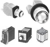
What Components Actually Define System Behavior?
System behavior is defined by how pressure is created, modified, routed, and converted into motion, meaning each component has a distinct and measurable role. Failures do not first occur at the system level. They occur at specific points where one of these functions breaks down.
After understanding the loop, the focus shifts to the physical components that shape it. Treating all components as interchangeable leads to poor diagnostics and poor design. Each category controls a different part of the pressure signal. That connection allows systems to be evaluated based on function rather than assumptions.
Component Roles
|
Function |
Role |
EKCI category |
|
Air control |
Stabilizes pressure |
Regulators |
|
Timing |
Controls delay and sequence |
Pneumatic timers |
|
Routing |
Directs airflow |
Pneumatic valves |
|
Counting |
Tracks or triggers events |
Counters |
|
Indication |
Displays pressure state |
Indicators |
|
Motion |
Converts pressure to force |
Cylinders |
What Does a Pneumatic Timer Actually Control?
A pneumatic timer controls when a pressure signal is allowed to pass, exhaust, or shift, enabling controlled delays within a system without electrical input. Timing is created by regulating airflow into or out of a chamber until a pressure threshold is reached.
With component roles established, timing becomes the first specialized function that directly impacts system behavior. Without controlled delay, systems execute actions too early or overlap operations. That leads to mechanical conflict or incomplete cycles. Timers introduce order into a sequence, and timing accuracy depends on stable air conditions.
Typical Timing Use Cases
- Delay before actuation
- Sequence control between operations
- Controlled release or reset
How Do Valves Control System Logic?
Valves control system logic by determining where air flows, when it flows, and when it stops, making them the primary decision mechanism in a pneumatic system. Incorrect valve behavior results in incorrect system outcomes regardless of other components.
After timing is understood, routing becomes the next control layer. The system must decide where the signal goes, not just when it moves. Valves entirely control that decision. Valves translate pressure changes into system logic. It's important to note that incorrect routing leads directly to system failure.
Valve Control Roles
- Directional control
- Signal switching
- Exhaust and reset
Which Cylinder Standard Should Be Used and Why?
Cylinder selection must match load requirements, mounting standards, and system constraints, not just size or availability. Incorrect selection leads to misalignment, premature wear, or integration failure.
Once control logic is defined, attention shifts to how the system produces movement. The actuator is where pressure becomes force, and that introduces physical constraints. Ignoring those constraints leads to poor system performance even when control logic is correct. Cylinder standards affect real-world compatibility and reliability.
Cylinder Comparison
|
Standard |
Best use |
|
ISO 6432 |
Compact systems |
|
ISO 15552 |
General industrial |
|
CNOMO |
Legacy compatibility |
Where Do Pneumatic Control Systems Outperform Electrical Control?
Pneumatic systems perform best where mechanical reliability, simplicity, and serviceability outweigh the need for digital precision or complex logic. They are particularly effective in environments with contamination, vibration, or limited electrical infrastructure.
With system structure fully defined, the next step is evaluating where this approach is actually the correct choice. Pneumatics are often compared to electrical systems without context. That leads to misuse in both directions.
Best-Fit Environments
- Industrial automation
- HVAC control systems
- Food processing
- Medical and lab devices
What Causes Most Pneumatic System Failures?
Most failures are caused by air quality issues, leaks, pressure instability, or incorrect component selection rather than system design itself. When pressure is inconsistent, the entire control loop becomes unreliable.
Understanding strengths leads directly to understanding failure points. Most issues come from conditions that disrupt pressure stability, not from component defects. Without identifying these causes, troubleshooting becomes reactive.
Failure Drivers
|
Issue |
Result |
|
Air leaks |
Pressure loss |
|
Contamination |
Component wear |
|
Poor regulation |
Timing drift |
|
Bad routing |
Signal delay |
When Should Pneumatic Control Not Be Used?
Pneumatic control should not be used when high precision, complex logic, or digital integration is required. In those cases, electronic or PLC-based systems provide better control. After defining strengths and failure modes, the system’s limits must be clearly established. No control method applies universally. Ignoring those limits leads to inefficient or unstable systems. Determining when pneumatic controls becomes the wrong choice prevents misuse and improves system design decisions.
What Separates a Reliable Pneumatic Control System from a Problematic One?
A reliable pneumatic control system is built around stable air supply, correct signal logic, and components that match the actual motion, timing, and service conditions of the machine. Most performance problems do not come from pneumatic control as a concept. They come from poor pressure regulation, contaminated air, misapplied valves, incorrect timing ranges, or actuator choices that do not match the load.
By this point, the pattern is clear: system performance is determined by how well the control loop is maintained under real conditions. Each section has shown how pressure stability, component roles, and system logic interact. Looking at any one component in isolation does not explain system behavior. The entire control path must be considered as a single working structure.
This is why pneumatic control still holds value across industrial automation, HVAC, medical equipment, and production systems. The decision is not whether pneumatic control is outdated. The decision is whether the control method fits the environment, the equipment, and the operational demands. When those conditions are aligned, pneumatic systems remain a precise and practical solution rather than a compromise.
Related Reading:
- Pneumatics and Robots
Pneumatic systems are being used in the creation of different types of robot. There are several reasons, such as safety, efficiency, and ease, as to why pneumatic systems are utilized in the robotics industry. - Pneumatics and Hydraulics
- Long Delay Timers


- Ellis/Kuhnke Controls
132 Lewis Street Unit A-2, Eatontown, N.J. 07724
Phone: 1-800-221-0714
Fax: 732-291-8154
Email: Info@ekci.com
- Home Pneumatic Controls Technical Info CAD Drawings Contact Us Pneumatic Timers Blog Site Map